A Guide To Custom Textures in Vectorworks
This tutorial outlines how to make your own Renderworks Textures from scratch.
Well-constructed textures can emulate photorealistic surfaces when rendered with Renderworks.
Click the button below to download an optional Vectorworks file to work in as you experiment with textures.
PART 1: Creating a Simple Image-Based Texture
1.1 Making A New Texture Via the Resource Manager
Textures are resources, meaning they are assets that can easily be shared between files.
Textures are just one type of resource that can be found in the Resource Manager (RM).
If your RM palette is missing, turn it on via Window > Palettes.
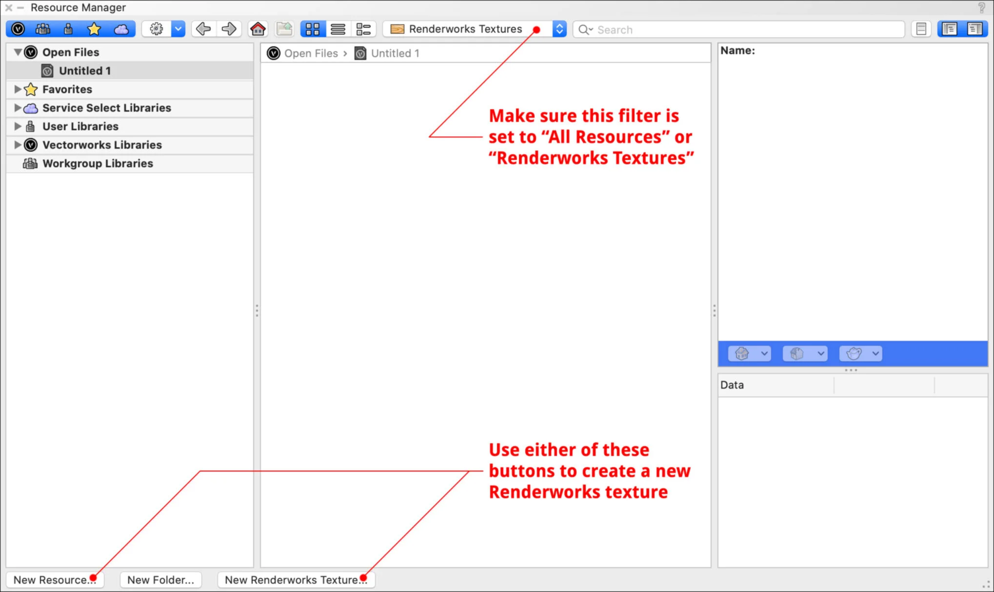
Make sure the filter at the top center of the RM is set to either “All Resources” or “Renderworks Textures.”
If you’re looking for existing library textures, you can use the Search field in the upper right corner.
To create a new texture from scratch, click the New Resource button in the lower lefthand corner of the RM, then choose Renderworks Texture and click OK. The Edit Texture window will appear.
You will need to have an image file on your hard drive to use for this exercise. See my links page for sources of free texture images.
1.2 Overview of “Edit Texture” Window
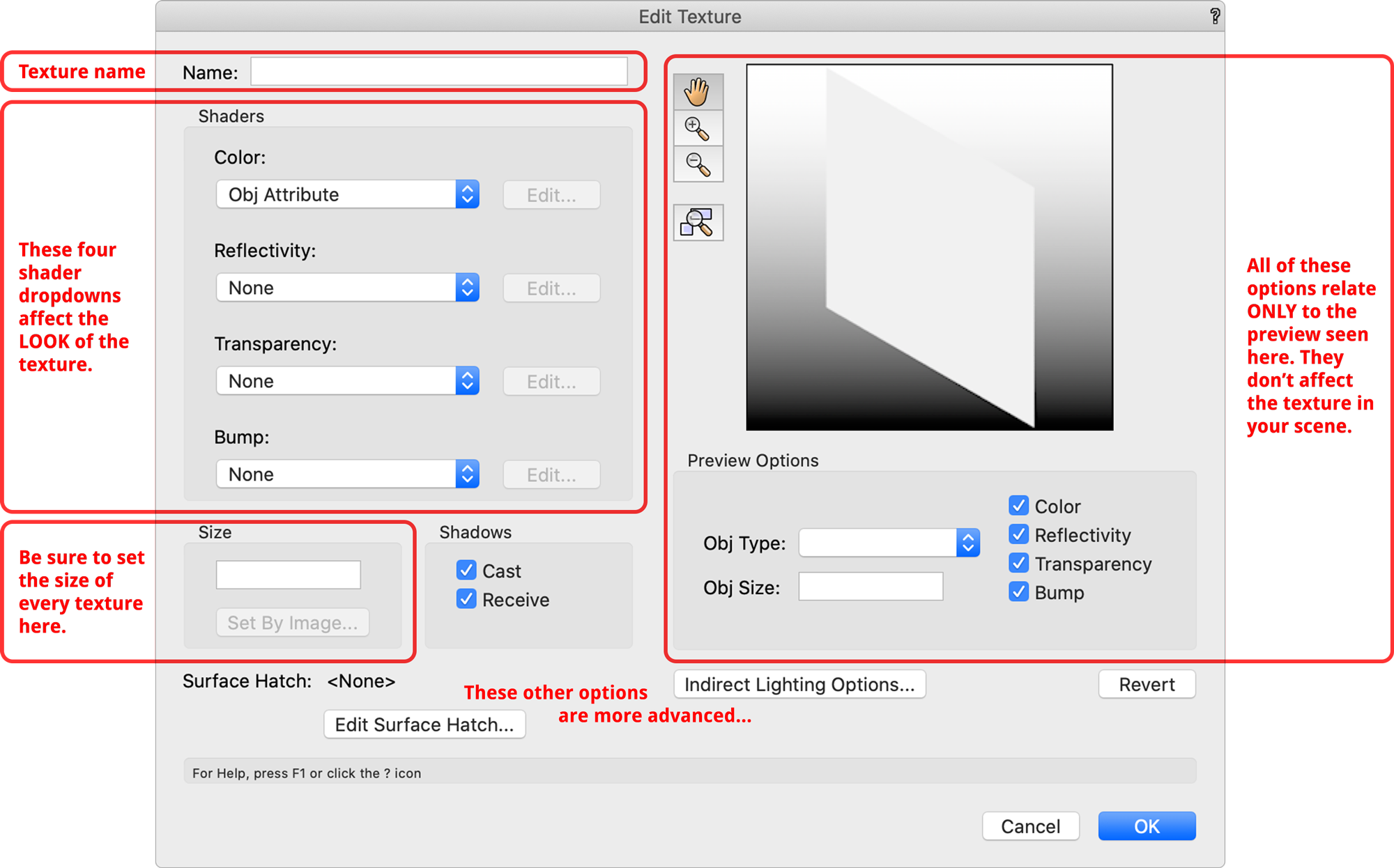
1.3 Naming Your Texture
Always give your texture a descriptive name.
For example, instead of “concrete” try naming it “Concrete Rough Weathered” or “Concrete Polished.”
Why put the word “Concrete” first? That way when resources are alphabetized, all of the concrete textures are near each other. Always start with the category name (wood, brick, paint, etc.) followed by a brief description.
You may seen the letters “RT” used in texture names, which stands for Renderworks Texture.
If you plan on exporting to Unreal, you might explore a naming convention such as “MI_ConcreteRoughWeathered” (Material Instance).
1.4 Importing Image & Setting the Texture Size
Set the Color shader dropdown to Image.
In the pop-up, choose Import Image then find the appropriate file on your hard drive and click OK.
When you see the Edit Image Color window, click OK again.
In the Size field (lower left area of the Edit Texture window), type in a measurement that represents the width of your image as it should appear on a surface. The height stays proportional.
Textures in Vectorworks work differently than in programs based on UVW mapping. In Vectorworks each texture has a real-world size. This is the default size when applied to an object, and it will be tiled as needed depending on the object size.
Individual objects then have a scaling factor (default “1”) which allows you to make the texture larger or smaller per object, if needed.
If you don’t know the overall width that the image should be, you can click the Set By Image button, then drag the endpoints of the line widget until it lines up with an object in the image (such as an individual brick or plank of wood). Type the length of that line and click OK, then Vectorworks proportionally calculates what the overall Width should be and enters this into the Size field for you.
1.5 Notes on Terminology
In Vectorworks, a texture refers to what some programs may call a material.
A shader is any of the four dropdowns in the Edit Texture window where settings are applied (Color, Reflectivity, Transparency, Bump). Some programs might call these channels or slots.
A Vectorworks texture can have images loaded in any of the four shaders; in other programs this might be described as loading textures into the material.
To put that another way, some programs refer to the original image files (JPGs, PNGs) as “textures,” while in Vectorworks the word “texture” refers to the finished product which can be applied to objects.
Images can also be referred to as “maps.”
It’s also important to note that when you load an image into a texture in Vectorworks, that image is embedded into the file, meaning it’s not linked to the original image file on your hard drive.
This makes sharing and organizing files easy because you never have to worry about externally referenced image files (although this does increase file size).
1.6 Applying Your Texture to an Object
There are multiple ways to approach applying a texture to an object.
One way is to select the object and then double click the texture thumbnail in the Resource Manager.
For now set the render mode to Shaded (OpenGL) to see solid surfaces.
An object must have a fill for textures to appear. If the fill is set to None then the object will appear wireframe, even in OpenGL.
Texture mapping is an entire subject of its own, so this tutorial focuses only on the settings of the texture itself.
If you want to explore texture mapping, look at the Render tab of the Object Info Palette. Additional control is available with the Attribute Mapping Tool.
The texture you made lives in the Resource Manager of this file. If you want to Edit the texture definition further, right click the thumbnail in the RM and choose Edit.
PART 2: Shaders Overview
2.1 Shader Categories
In Vectorworks each texture has four shaders available that affect how the rendered surface looks:
The Color shader sets the base color pixels of a surface (a.k.a. albedo or diffuse). Think of it like the flat paint color or wallpaper pattern.
The Reflectivity shader controls how the texture interacts with light and reflections. Think of it like the sheen of the paint, or whether it might be a mirrored surface, for example. Additionally, self-illuminating textures can be set with the “Glow” option.
The Transparency shader gives control over the opacity of the texture, either for the entire material (such as glass), or selectively with an Image Mask (useful for cutout prop textures, CNC patterns, etc.)
The Bump shader provides information about the dimensional height that a rough or uneven surface would have in real life, even though the object is modeled with a perfectly flat surface in Vectorworks (for example, think of the dimensionality that a real brick wall has). Adding Bump settings will cause light that scrapes along the surface to create highlights and shadows along the hypothetical crests and valleys, providing additional realism.
Normal maps are not supported in Vectorworks, but greyscale displacement maps are.
Each shader dropdown can only be set to one option. (In this way, Vectorworks textures are simpler than in advanced 3D rendering programs such as Cinema4D or 3ds Max which allow multiple shader layers in each category, along with additional categories).
The final rendered result depends on which shaders are used and how they interact with each other. It’s also highly reliant on the lighting in your scene.
2.2 Overview of All Shader Options
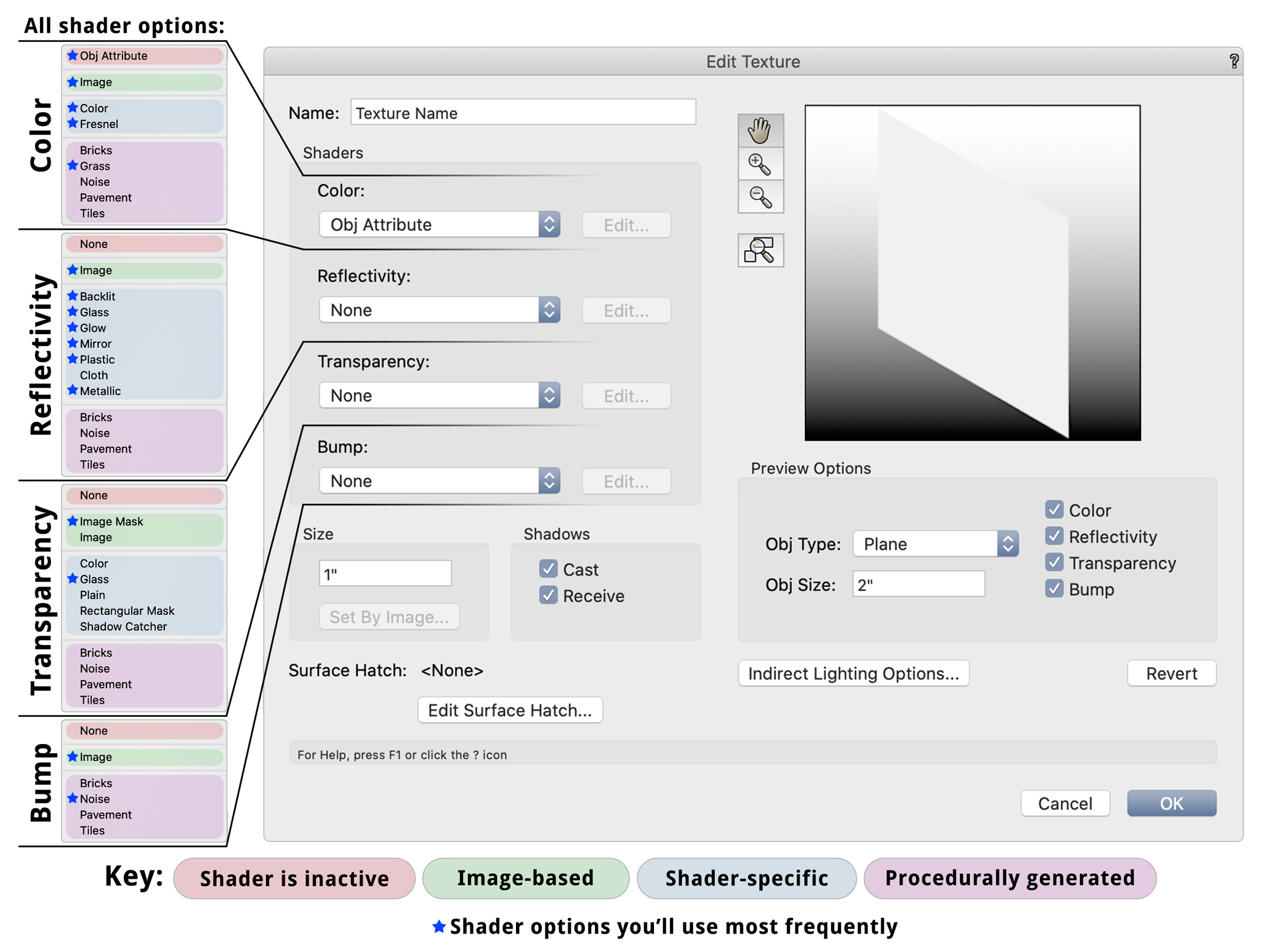
I’ve included an image below showing all of the available shader options, and how each dropdown is divided into sections.
The blue stars indicate options that you’re likely to use most frequently. These are the shader options covered in detail on this page.
Don’t feel like you need to master every single texture option right off the bat. Use this page as a roadmap of where to start, and then continue experimenting from there. Different combinations of shaders produce different results.
2.3 A Note About Textures in Shaded Render (OpenGL)
Shaded is a simplistic render mode meant for speed, not realism. It used to be called OpenGL.
Shaded shows only an approximation of many texture settings such as Reflectivity, Transparency, and Bump. Shaded was improved in VW2023 with the addition of lighting & reflection control within Shaded Settings, but it’s still optimized for speed, not photorealism.
For fully-rendered textures you must use a Renderworks style (Fast, Final Quality, or ideally a custom Renderworks Style).
Be aware that even Renderworks Styles can have individual settings disabled, such as grass or displacement mapping.
PART 3: Details of Common Shader Options
3.1 Color Shader - Object Attribute
The first option in the Color shader dropdown is named Object Attribute, not “None” like the other three shaders. Why is that?
It’s impossible to have a surface that doesn’t have any base color, so when you set the Color shader to “Object Attribute” the Fill Color from the Attributes Palette will be used as a base color instead. Then the Color isn’t controlled by the texture, but by the Attributes Palette.
This is useful if you want the texture to apply the Reflectivity shader (such as a glossy plastic sheen), while still being able to assign different solid colors to different objects with the Attributes Palette. This can be done with a single texture as shown below (the plastic shader is described later).

These objects all have the same Texture. The Color shader is set to “Object Attribute.”
3.2 Color Shader - Image
This is the option you’ll use most frequently, as a majority of the textures we use are image-based.
Importing an image was already covered above. If you want to switch out an image in an existing texture, click the Edit button to the right of the Color shader dropdown, then click Change Image. Find the image on your hard drive and click OK.
Remember that because there is no live-link reference to the file on your hard drive, if you change that image file (in Photoshop for example), you’ll need to import it again to replace the previously-imported image in Vectorworks.
Be aware of how many pixels are in your image; the larger the image the longer it will take to render, so you have to balance speed with quality. You’ll learn the sweet spot with experience.
For example, it’s likely you don’t need 4k-quality textures unless you’re doing super high-end photorealistic renderings with close-ups.
Unlike some rendering software, images do not need to be square, nor do they need to be in base-2 increments (512, 1024, 2048, etc.). Vectorworks is quite forgiving with the image size.
Images are always kept proportional when tiling on surfaces, so the original aspect ratio of the image is important. (This is actually my favorite thing about texturing in Vectorworks, by the way!)
Remember to set the texture Width as described earlier.
Vectorworks supports the following image formats: JPG, PNG, PSD, TIF, TGA, BMP, PCT, PNT, QTI, and SGI.
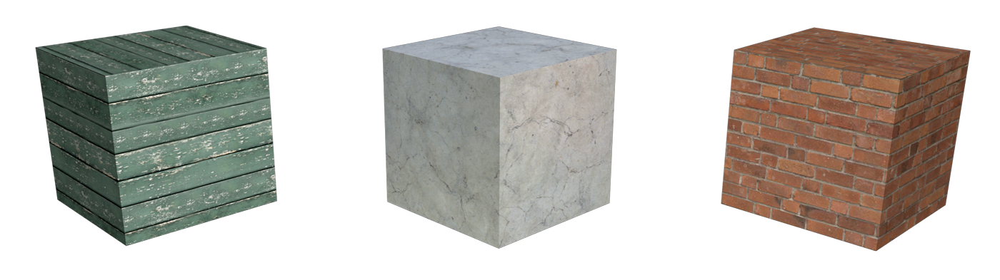
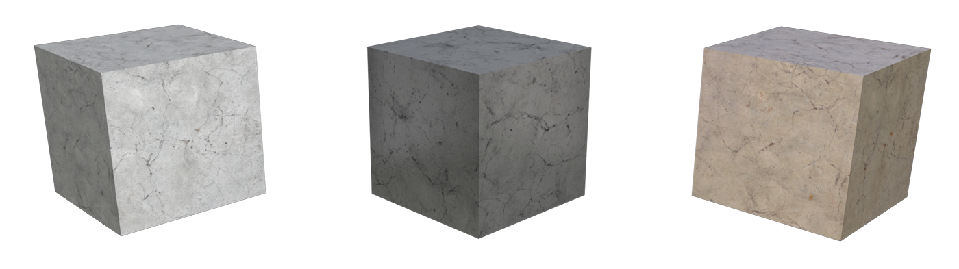
Examples of different image-based textures.
The Edit Image Color window that appears when you click the Edit button has a few other functions:
You can do basic edits such as rotating, mirroring, and inverting the image.
You can click the Image Effects button to do some basic filtering of the image (such as contrast, saturation, etc.). Note that these apply permanently to the image when you click OK.
You can choose a Filter Color to blend with the original image. The blend mode is similar to Multiply in Photoshop (it can only darken the image, not lighten).
No Filter is default, meaning the original image is used as-is.
Use Object Fill will tint the texture using the fill color of each individual object as set in the Attributes Palette. This allows the image to be blended with different colors on a per-object basis all using a single texture (see image below).
Use Chosen Color lets you specify one particular color to tint the texture.
These three objects have the same texture. It has the Filter Color set to “Use Object Fill.”
3.3 Color Shader - Color
This option is similar to the “Object Attribute” option above because it results in a solid color, but here you specify a single particular color for the texture definition, rather than it being defined on a per-object basis.
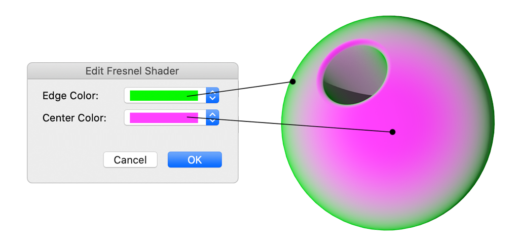
3.4 Color Shader - Fresnel
Fresnel also uses solid colors but it uses two colors instead of one.
The Center color is shown on surfaces that are facing straight at the camera.
The Edge color is shown on surfaces that are angled away from the camera view.
As a curved surface moves from straight-on to tangent, the Edge and Center colors are blended together based on the grazing angle.
Fresnel only renders in Renderworks modes. In Shaded render / OpenGL, only the “Center” color is displayed.
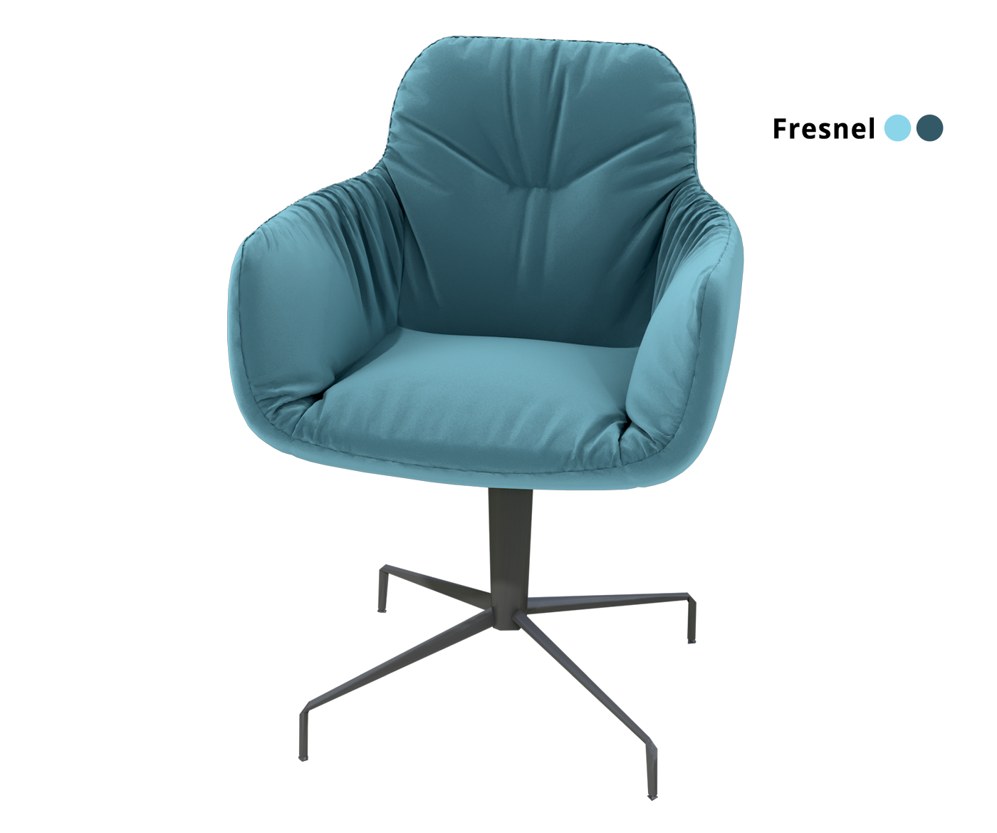
Fresnel is useful for adding additional definition to spheres and solid color objects, along with defining the color of velvet (below).

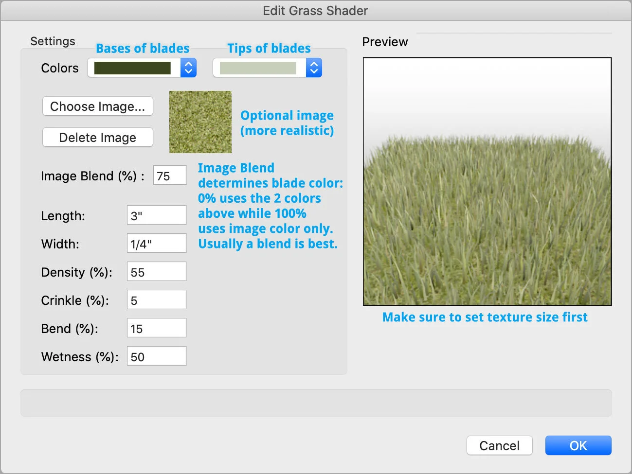
3.5 Color Shader - Grass
The Grass shader option renders 3D blades of grass which can greatly add the realism of an exterior scene.
The geometry is modeled as a simple flat surface, and when rendered the blades of grass appear.
The grass option can dramatically slow down render time, particularly if it’s a large area of grass and/or the density is set really high.
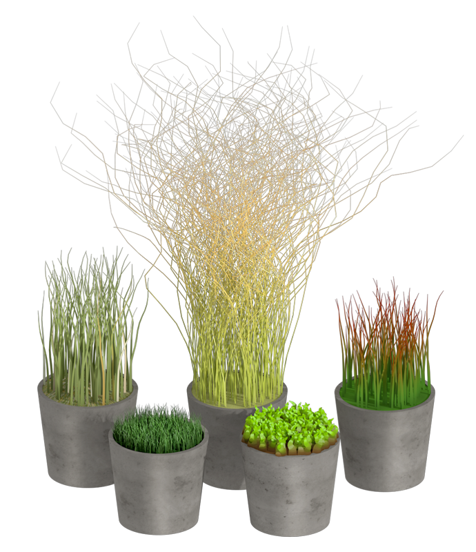
Examples of procedurally-generated 3D grass using the Grass shader.
The textures are applied to circles extruded to 0”.
Grass is an option that can be enabled or disabled in a Renderworks Style. It’s always off in Fast Renderworks and always on in Final Quality Renderworks. When grass is disabled, the ground color/image is still rendered.
The grass shader can be creatively used for fur and rugs as well.
3.6 Reflectivity Shader - Image
Loading an image into the Reflectivity shader will use that image as a map of how each pixel should reflect.
White pixels are full reflection, black pixels are no reflection, and grey pixels reflect based on value.
Colored pixels will reflect their color.
Typically you should load an image with the same aspect ratio as the image in the Color shader (if applicable).
In the Edit window you can scale down the maximum amount of Reflection for the image (default 100%).
The term “reflection” within texture settings always refers to ray-traced reflections of other objects in the scene.
Blurriness % does not blur the image used in this shader, but rather blurs whatever is being reflected in the surface. Typical range is 0-40%. Blurriness does not render in Fast Renderworks.
The typical application of an image-based Reflectivity shader is to load a black-and-white image representing areas that are shiny versus not shiny. For example, a porcelain tile texture would use a full color image in the Color shader, and a black and white image in the Reflectivity shader. The grout lines would be a black grid (not reflective), and the tiles would be white (shiny).
The Reflectivity shader is only rendered in Renderworks styles, not OpenGL.

3.7 Reflectivity Shader - Backlit
This setting is useful when you have a Light object behind the surface that the texture is applied to. Don’t confuse it with Glow (see 3.9), which is a self-illuminated textured. Backlit requires an external light source.
There are two common uses of this option:
Lamp shades (again, assuming you have a Light inside it).
I recommend sweeping a single line around a locus point to create the lampshade. This seems to work better than a lampshade with actual thickness.
For the light I recommend a Point Light with Realistic Falloff.
Shadow-play screens, where something casts a shadow from behind producing a silhouette on the surface.
In this case you’d use a Spotlight or Directional Light as the light source.
The Color option determines the color of the back-illuminated areas, which is also blended with the color of the light source.
Reflection % can add reflections of other objects in the scene, and Blurriness % can blur those reflections.
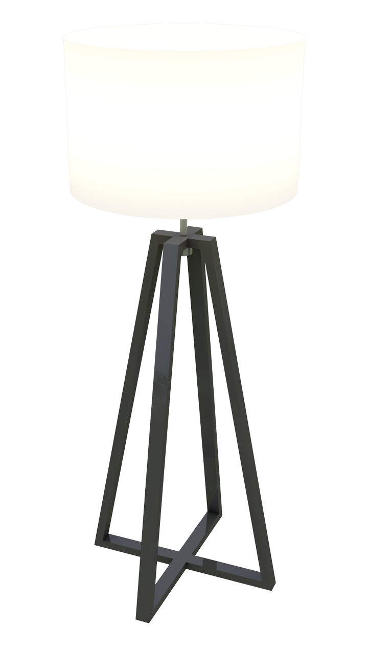
Backlit lamp shade with Point Light inside

Backlit shadow screen example
3.8 Reflectivity Shader - Glass (a.k.a. Fresnel)
The Glass reflectivity setting only affects reflections, not transparency. It can be used to create a realistic glass texture in conjunction with the Glass transparency shader (see 3.14).
Glass reflectivity is based on a fresnel paradigm (see 3.4), where you specify an Edge and a Center color related to the angle of the surface as it appears to the viewer. This results in reflections based on angle of incidence.
A common glass texture will have the Edge color as white (fully reflective) and the Center as black (no reflection). This way you can see through glass if you’re looking straight at it, but when you’re at steeper angles you get more reflections.
If you want more reflections in the straight-on areas, brighten the Center color.
Think of the colors as reflection values between 0 and 100%, rather than the literal colors.

Glass reflectivity demonstrated on a solid orange object
You can also specify Blurriness % which will soften the reflections.
This shader can also be used for materials that aren’t glass - that’s really just the name of the shader. Any time that you want to have fresnel-based reflections you can use the Glass reflectivity option (and in fact, most objects have some degree of fresnel reflectivity rather than uniform).
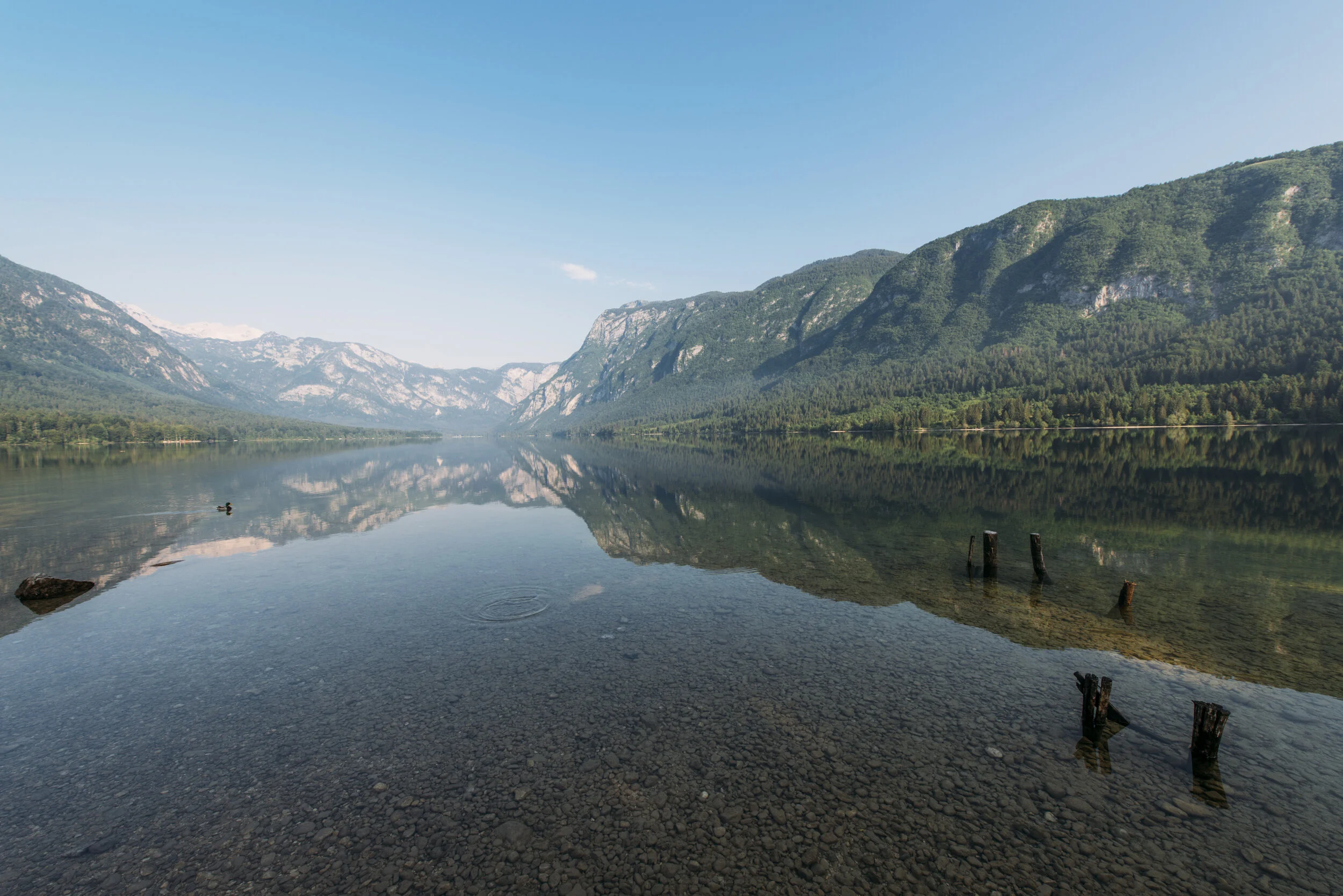
Ever notice that when you look straight through water you can see through it, but at steeper angles you start to see reflections? That’s also due to fresnel reflectivity!
3.9 Reflectivity Shader - Glow
Glow is a frequently-used Reflectivity option, as it creates self-illuminated and emissive textures. Here are some examples:
Lightboxes (common in variety TV / game shows). No need to actually put lights inside the unit, just use a Glow texture.
Remember the Color shader could contain a color image of a gradient.
Television screens and LED video walls.
Backings / translites.
Visible light bulb geometry and neon.
Can be used as an actual source of light, such as recessed LED tape accent lighting.
The options in the Edit window are super important:
Brightness is of course how bright the surface is. 100% is default, but you can go higher than that. I commonly go up to 500% for bright white LED tape effects.
Emit Light needs to be checked if you want the surface to illuminate other surfaces in the room. For this to work, Indirect Lighting needs to be turned on. For this reason I recommend using custom Renderworks Styles since they can enable Indirect Lighting automatically.
Add Matte Reflectivity is an important but poorly-named setting.
When this is off, surfaces using this texture are not affected by external lighting. Their brightness is controlled by the Glow Brightness alone. (Useful for image props that have lighting baked into their Color image).
When this is on, surfaces do react to external lighting on top of their on Glow setting.
Reflection % sets the reflection amount, and Blurriness % blurs the reflections.

3.10 Reflectivity Shader - Mirror
The Mirror reflectivity option is useful for… mirrors.
The mirror Color choice (default white for “regular” mirror) will recolor the entire mirrored surface, emulating a colored mirror/acrylic or polished metal. The value correlates with the amount of reflection.
The Color shader (see 3.3 above) should typically be set to solid black when using Mirror reflectivity.
The only difference between Mirror reflectivity and Glass reflectivity (see 3.8) is that Mirror is a single value and Glass is two values (fresnel).

This colorful mirror effect could be achieved with Mirror Reflectivity.
3.11 Reflectivity Shader - Plastic
Plastic reflectivity is the only non-metallic option that creates specular highlights, which are essentially hot-spots that appear on surfaces based on the position of lights in the scene.
This option is great for adding a bit of a sheen without showing literal reflections of other objects. It works really well on curved surfaces and fillets, and not as well on flat surfaces.
The Color choice here will tint the specular highlights with the chosen color (default is white).
Note that if a light source is colored, the highlight will take on that color as well.
Brightness % is the intensity of the specular highlights.
Roughness % is the size/spread of the highlights. A lower number is small and sharp, while a bigger number is large and diffuse.
Reflection % and Blurriness % work the same as in the shaders above, allowing you to add some ray-traced reflections of other objects in the scene. (The reflection cannot be colored like it can with the Mirror option.)

3.12 Reflectivity Shader - Metallic
The Metallic reflectivity option is mainly used for shiny metal materials. It uses multiple layers of reflection algorithms to produce the effect.
Metals only look like metal when they have something to reflect, so the lighting in the rest of the scene is very important.
Instead of making your own metallic texture from scratch, try searching for “metal” in the Resource Manager search field. There are pre-made textures that come with Vectorworks that you can use and experiment with.

3.13 Transparency Shader - Image Mask
When you want image-based transparency you’ll typically want to use the Image Mask option.
If you want a colored transparency effect (such as a stained glass window or colored gobo) then use the Image transparency option instead of Image Mask.
For best results use an image with the same aspect ratio as the image in the Color shader.
Ideally the image is either a PNG with embedded transparency or a black and white transparency map (where black is opaque and white is transparent). Either works fine.
When you import an image you’re presented with three options:
Grayscale Pixels: Choose this option to use the value of each pixel as the amount of transparency, usually with a black and white image. Technically you can use a color image, though it only uses the value data. If you’ve downloaded a B&W alpha mask from the internet, this is where to load it.
Transparent Color: This lets you sample a color in the image that Vectorworks then makes transparent (kind of like a chroma key). However this usually leads to jagged edges so I don’t recommend it. Instead, take the image into Photoshop and cut it out there and use the next option.
Alpha Channel: This option is available when importing a PNG with embedded transparency. If you already cut out the object in Photoshop, export a PNG and use this option to get that exact transparency in Vectorworks. I use this option the most.

Examples of objects using Image Masks for transparency.
3.14 Transparency Shader - Glass
This is the shader option that makes glass look like glass. (Make sure to set a reflectivity as well.)
For typical glass surfaces I usually use the default texture that comes with Vectorworks called Glass Clear RT. You don’t necessarily have to make your own.
A glass texture usually has black or a dark color in the Color shader (see 3.3).
Transmission (%) determines how transparent the glass is. 0% is opaque and 100% is clear. Common glass is in the 90-95% range.
Index of Refraction is related to refractions caused by looking through the glass. The index number determines how the texture changes the direction of light rays as they move through the medium. A value of 1 results in no refraction. Water and ice are around 1.3, and glass is typically 1.5-1.6 (but you can reduce this if the distortion is distracting).
Color is typically white, but if you want colored glass set that here (and leave the Color shader set to black).
Blurriness % blurs objects seen through the glass. Blurred glass appears frosted and takes longer to render.
Absorption Color defines the color that appears when a ray of light has traveled through a thicker area of glass (as determined below).
Absorption Distance defines the distance a ray of light has to travel before Absorption Color replaces the original Color. The lower the value, the more intense the Absorption Color is.
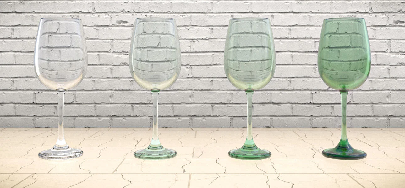
Example showing different absorption distances in a wine glass.
3.15 Bump Shader - Image
Like the other three shaders, the Bump shader can utilize an image to determine the results. The bump image represents the uneven surface detail that the real-life material might have, and causes additional highlights and shadows to render (depending on the lighting of the scene).
Bump also affects the way reflections and refractions render.
The bump map is based on pixel values: the brighter a pixel, the more proud of the surface that spot is. Therefore, black is for recesses, and white is for protrusions. Pixels that are 50% gray remain unchanged. Technically a color image can be loaded, but only the value data will affect the bump.
Bump Strength sets the amplitude of the bump effect. This is usually the most important setting to adjust and may require some experimentation depending on the size of the texture and viewing distance.
Make sure the surface has lighting to react to when doing test renders.
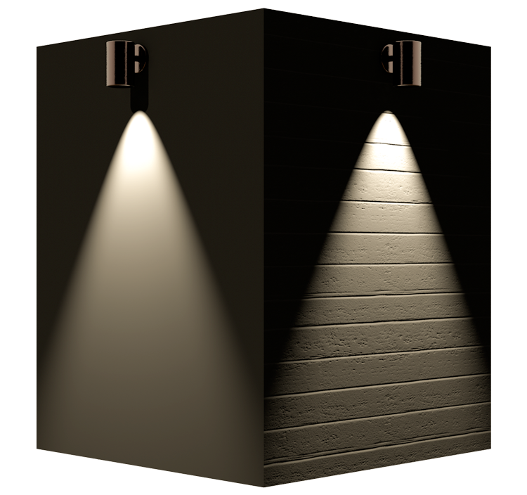
Both of these planes are a solid color. The one on the right has a bump map which creates the highlights and shadows. In practice you’d combine this with a matching color image in the Color shader for the best photorealistic effect.
Parallax Offset enhances the dimensional illusion of the bump effect by having the surface occlude itself when viewed at oblique angles (middle image below). However, the silhouette of the 3D object remains unchanged. It’s like a simpler and less expensive version of Displacement Mapping.
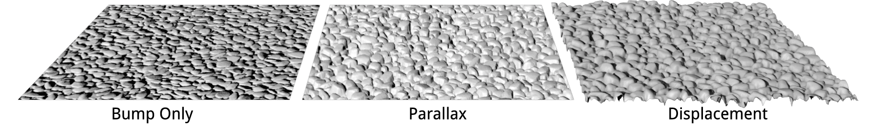
Displacement Mapping will render the geometry as physically displaced, leading to highly realistic results but also adding a lot of render time. See rightmost image above. Use only when needed.
Height is the maximum displacement amount, typically between 0” and 2”. A value of 0” means no Displacement. When a Height value is entered, areas of the image that are pure white will protrude by that distance, and areas that are pure black will recede by that distance. 50% gray will remain in place. Therefore the total possible depth is twice the value of this Height field, since it can both protrude and recede. Higher height values lead to longer render times.
Detail sets the level of detail for displacement mapping (sort of like how sharp or smooth the results are). Requirements and results will vary depending on the image used and the size of the surface.
Self-Shadowing adds shadows to the displaced geometry, increasing realism as well as rendering time.
Displacement Mapping only renders in Final Quality Renderworks and in Renderworks Styles with it enabled. There is also a Quality setting within the Renderworks Style options that greatly affects the final result.
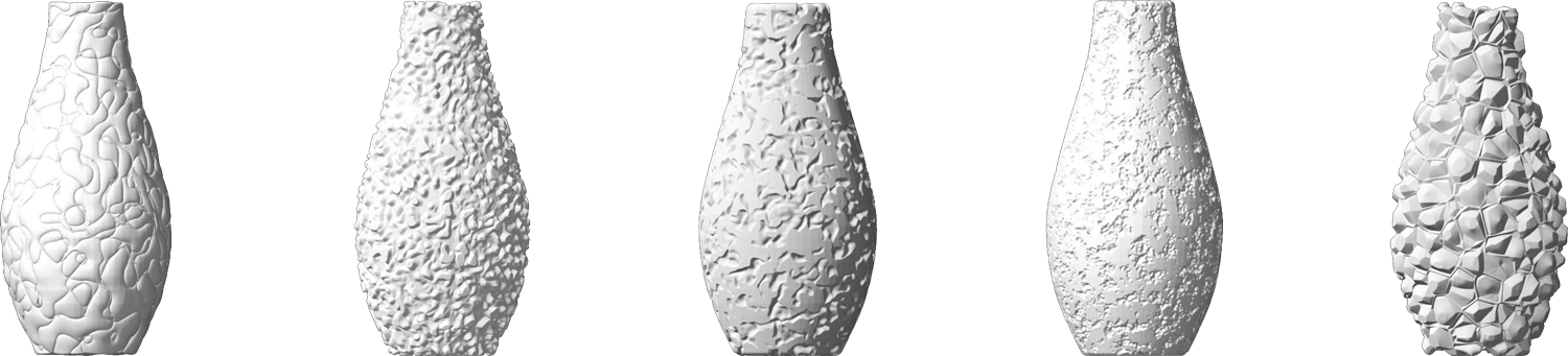
3.16 Bump Shader - Noise
The effect of this shader option is the same as an image-based bump, above, but instead of using an imported image, the greyscale bump map is procedurally generated within Vectorworks as a non-repeating / random pattern. There are numerous algorithms to choose from, and each can be dramatically affected by changes to its parameters. A few examples are below:
3.17 Extracting an Image from an Existing Texture
Earlier we covered how to import an image into a Renderworks Texture. But what if you already have a Texture and want to edit the contained image in Photoshop, but you don’t have the original source file?
Simply right click the texture thumbnail in the Resource Manager and choose Extract Image(s). This will save any images used in the texture to your hard drive, which you can then edit and re-import as needed.
3.18 Conclusion
Thanks for taking the time to read this page! I hope you found it helpful, and remember that texturing becomes easier and faster with time and practice. There’s a lot that wasn’t covered here, but this page should serve as a strong foundation for continued experimentation.
If you have questions or comments please share them with me using the form below. Thank you!